

Products
01


Technology Of CAT.6A Data Cable
Introduction
Faced with users' increasing attention to network security and the increasing demand for network bandwidth, traditional Category 5e and Category 6 cabling products are gradually unable to adapt to the requirements of high bandwidth and high speed; at the same time, as the technology of such products continues to mature and develop, market competition is becoming more and more fierce, and the profit margins of manufacturers and system integrators are getting smaller and smaller; at the same time, digital communication symmetrical cables for integrated wiring systems are also constantly updated, and CAT.6A products are one of them, standing out with their 500MHz bandwidth and excellent performance.
CAT.6A cable is basically the same as that of CAT.6 cable, except that the wire diameter is a little thicker and the production cost is slightly higher than that of CAT.6 cable, but its maximum transmission frequency is doubled that of CAT.6 cable and only 100MHZ less than that of CAT.7 cable . However, its structure is simpler than that of CAT.7 cable . In order to achieve the maximum transmission frequency of 600MHZ, CAT.7 cable adopts the form of double shielding plus double-layer total shielding. Therefore, the manufacturing cost of CAT.6A cable is much lower than that of CAT.7 , so it is quite popular in the market and is increasingly showing its vitality.
In the foreseeable future, CAT. 6A system will become the mainstream of the market. This article briefly introduces the structure, performance, key control points in the manufacturing process and application prospects of this type of digital cable.
CAT. 6A digital cables
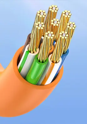
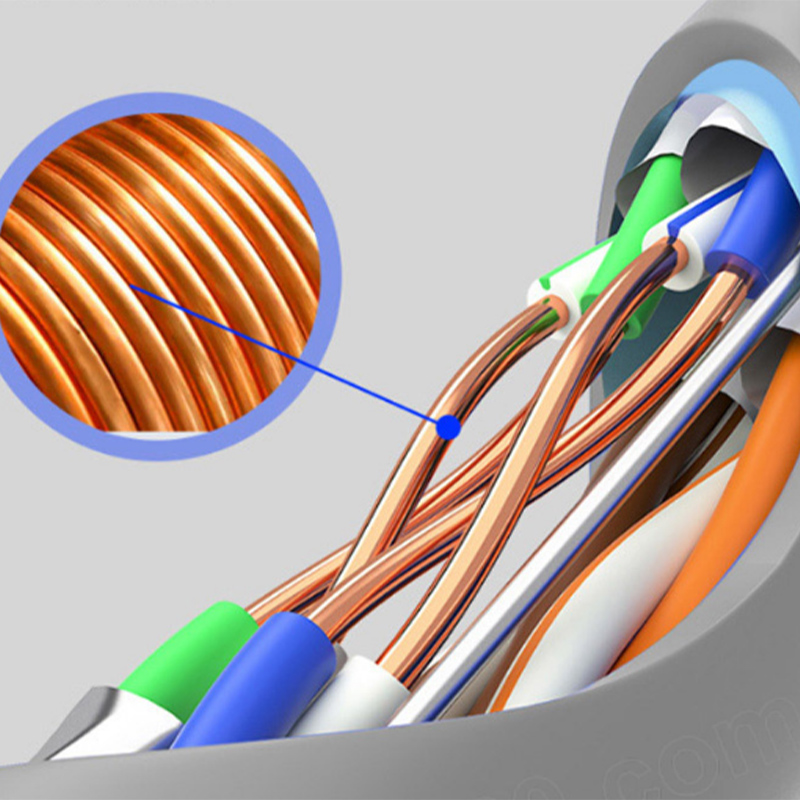
The performance indicators that are more difficult to pass in the technical indicators of digital communication cables include: attenuation, near-end crosstalk attenuation, etc. The attenuation performance of the cable can be improved by increasing the wire diameter and selecting better insulating materials; by designing a reasonable twisting pitch for the four pairs of wires, the near-end crosstalk and far-end crosstalk of the cable can achieve an optimal effect, stabilize the relative position of the four pairs of wires, and isolate the pairs from each other, reduce crosstalk interference, improve transmission quality, and ensure stable and reliable electrical performance. Because the relative position of the four pairs of wires will change due to external forces, it will affect the crosstalk attenuation performance of the finished cable, resulting in electrical performance that is not as good as the skeleton type. Therefore, the production process control, equipment performance, etc. are required to be high. In addition, when designing the cable, it is necessary to consider that each indicator should have a large margin to ensure that it can still meet the requirements after construction.
Effectively improving and ensuring the manufacturing accuracy, stability and uniformity of cables is the key to manufacturing high-performance data cables. The back-twist of the twisted pair is actually a pre-twist, that is, before the twisted pair is twisted, a certain twist is given to the single wire in the opposite direction to make the characteristic impedance and frequency curve more gentle. The increase in the back-twist rate can improve the electrical performance, but it also brings a side effect - the single wire structure is partially destroyed. Therefore, the back-twist rate should be controlled at about 10%, and it is best not to exceed 35%.
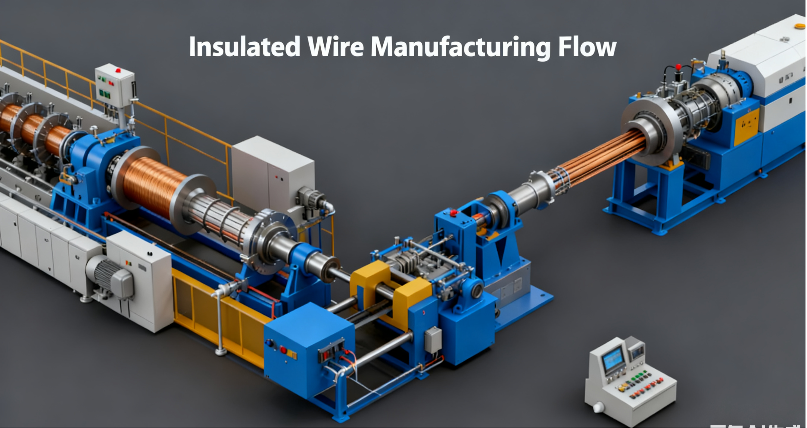
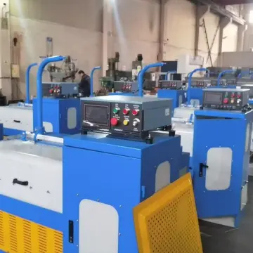
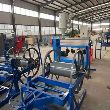
1 Main process flow chart of product production
Copper rod drawing → insulation extrusion → untwisting twisted pair → cabling (with skeleton) → shielding sheath → coiling
2 Product design basis
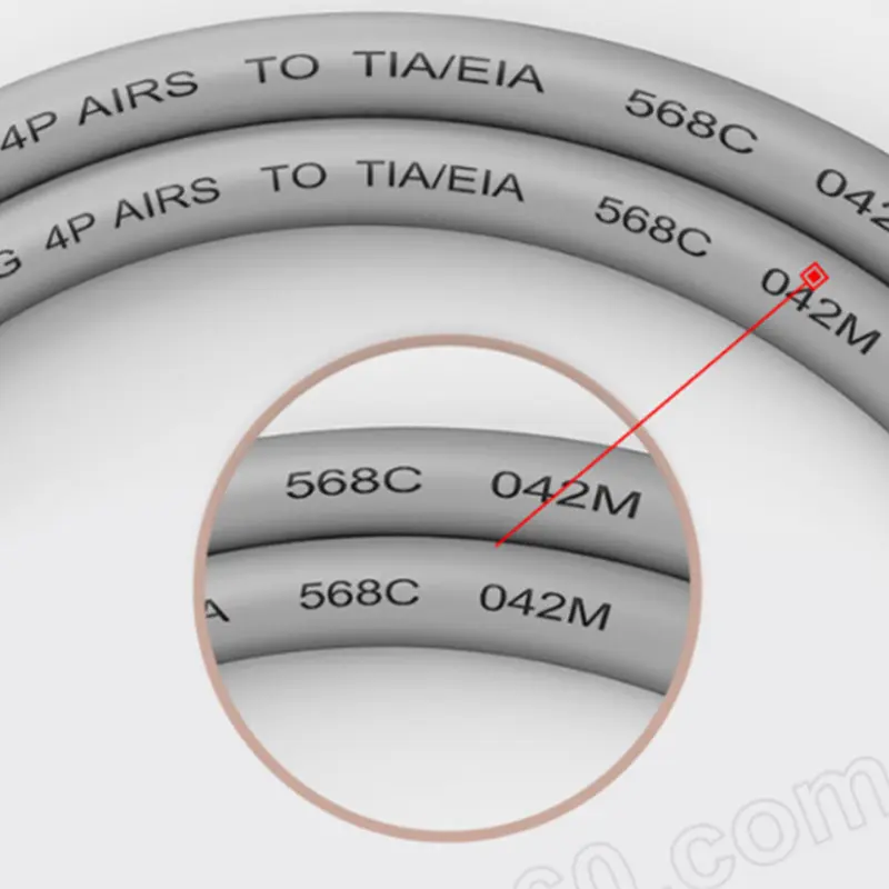
Determine product technical indicators based on TIA/EIA 568C.2-2009 related standards.
3. Process design
3.1 Structural design:
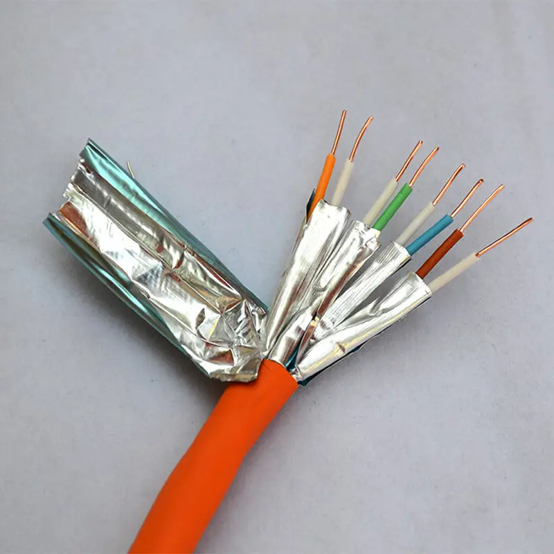
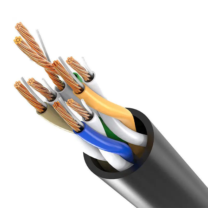
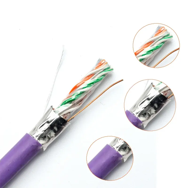
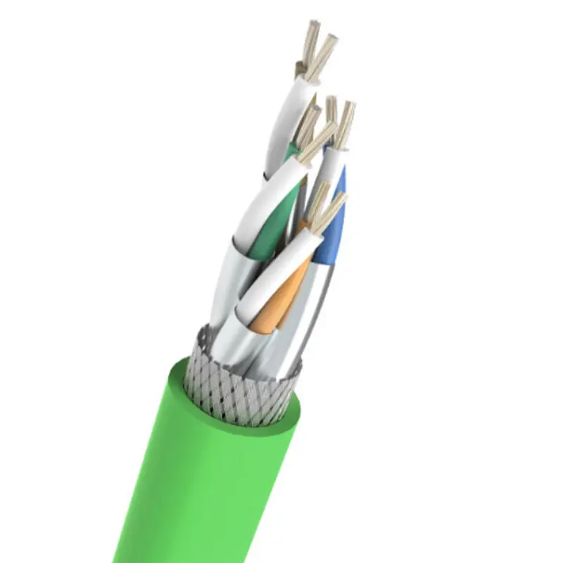
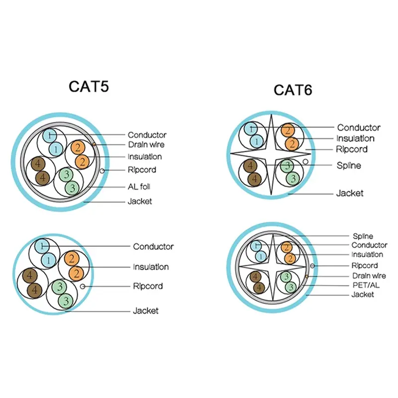
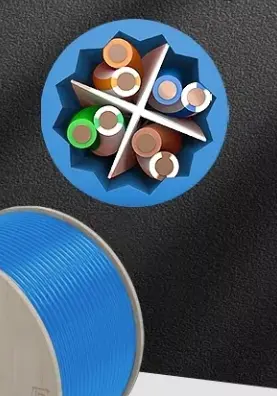
CAT. 6A cable has two models, UTP and FTP, but FTP is the main one. In order to ensure the stability of the symmetry of the CAT. 6A product structure, especially to ensure the smooth passing of the crosstalk attenuation index, CAT. 6A digital cable generally adopts a central cross skeleton structure, which is mainly used to isolate the line pairs and stabilize the cable core structure. The outer diameter of the cross skeleton is 5.0-5.5mm, the blade thickness is 0.6-0.7mm, and the material should be softer low-density polyethylene (LDPE). At present, some companies use "cavity" skeletons, which have great advantages in improving product impedance and crosstalk attenuation. However, when using cavity skeletons, the design and precision of the molding mold are very high during the cable production. The outer diameter of the finished cable is relatively large, which increases the manufacturing cost.
The shielded CAT. 6A cable structure uses metal shielding for the entire cable core. Due to the reflection and absorption of the metal shielding layer, it can better separate the surrounding electromagnetic field, effectively prevent the leakage of external electromagnetic interference signals and electromagnetic radiation from the inside of the cable, and has excellent electromagnetic compatibility and confidentiality, while also improving its own transmission stability.
3.2 Input impedance, attenuation and crosstalk index design:
The design of the insulation wire process is the top priority in the entire design process. According to the standard, CAT. 6A products generally use solid insulation. Of course, many manufacturers now use physical foaming for insulation wires based on customer needs and cost considerations, because the dielectric constant of air is the smallest. While the outer diameter of the single-wire insulation is reduced, the working capacitance will not increase, and the amount of insulation material used can be reduced by more than 50%, reducing the manufacturing cost. Today, under fierce market competition, how to compromise between excellent performance and cable cost is also crucial.
①. Characteristic Impedance (Characteristic Impedance) is represented by the letter Z and the unit is Ω
The materials and geometric dimensions of the conductor and insulation will affect the characteristic impedance value. Input impedance is one of the important indicators of CAT. 6A digital cable. Its calculation formula can be listed as:
Impedance upper limit: Zu = Zo*[(1+︱Ρ︱)/(1-︱Ρ︱)]
Impedance lower limit: Zl = Zo*[(1-︱Ρ︱)/(1+︱Ρ︱)]
Where Zo is 100Ω, ︱Ρ︱ is the modulus of reflection coefficient, ︱Ρ︱=10(-RL/20)
Combined with the template formula of impedance, it can be seen that the impedance requirements in the standard are slightly lowered. Considering that the impedance index of high -end CAT.6A and above products is prone to fluctuations at low and high frequencies, the standard allows a relatively large range of impedance fluctuations at low and high frequencies. For example, for CAT.6A products, the upper limit of impedance at 500MHz is 131.6Ω, and the lower limit of impedance is 76.0Ω, which is much easier to achieve than the 100±15Ω specified in other standards, and also meets the actual use requirements. Of course, low frequencies are also allowed to have appropriately large fluctuations. The provisions of this standard on impedance are relatively close to the actual product indicators of manufacturers.
② Attenuation is represented by the characters ATT , and the unit is decibel dB
Attenuation is mainly expressed as the ratio of the initial transmission end signal strength to the receiving end signal strength. It is the loss caused by the signal transmission along a certain length of cable. This value is directly related to the length of the cable and increases with the increase of frequency. Therefore, the smaller the value, the better.
CAT.6A cable: α≤1.820√f+0.0091f+0.250/√f (dB) , where f is the transmission frequency
In the above formula, affected by temperature, the increment for non-shielded cable in the temperature range of 20℃~40℃ is 0.4%/℃, and in the temperature range of 40℃~60℃ is 0.6%/℃, while the increment for shielded cable in the temperature range of 20℃~60℃ is 0.2%/℃. The standard also specifically points out that the performance of 1~4MHz is guaranteed by design, and there is no need to test the cable attenuation performance below 4MHz.
If solid insulation is used, the conductor diameter is generally controlled at 0.580mm to ensure that the low-frequency attenuation index is qualified, and the working capacitance is generally controlled at around 51nF/100m to ensure that the high-frequency attenuation index is passed; of course, the foaming process can also be used according to customer needs. In the foam insulation, the outer diameter of the single-wire insulation and the size of the capacitance in the water are controlled to ensure that the foaming degree of the insulation and the working capacitance of the finished cable can meet the design requirements.
③. Near End Crosstalk Attenuation (NEXT) in dB
NEXT is the ability to suppress the crosstalk interference signal generated by the transmission line pair and the adjacent line pair. It eliminates the crosstalk interference signal, so the larger the value, the better. The definition formula is as follows:
NEXT = 10㏒ (P1N/P2N) = 20㏑ (V1N/V2N) P1N main string pair input power
P2N is the output power of the serial pair at the near end of the cable
V1N is the input voltage of the main string pair, and V2N is the output voltage of the string pair near the cable end.
During the transmission process, capacitive coupling will occur between wire pairs, which will cause crosstalk in adjacent wire pairs. After twisting, the two adjacent pitches are crossed, and the relative positions of the two single wires a and b are interchanged. The polarities of the coupling capacitors are opposite, and they can cancel each other out after superposition. The closer the lengths of adjacent pitches are, the more consistent their positions are, the cleaner the cancellation is, and the smaller the crosstalk is. The distance between wire pairs will affect the size of the crosstalk. The farther the distance, the smaller the crosstalk. The use of a cross skeleton can increase the distance between wire pairs and make the wire pairs more symmetrical, which effectively improves NEXT. This can be achieved by appropriately increasing the thickness of the cross skeleton blades, and the NEXT index will be correspondingly better. The standard stipulates the value of this parameter as follows:
CAT.6A cable: NEXT≥75.3-15㏒f
It is particularly important to point out that CAT.6A products have added the test of external near-end crosstalk (ANEXT) indicators. At present, tester manufacturers are studying the method of on-site testing and installation system ANEXT. However, in the laboratory, the external crosstalk performance test of cables can be achieved. The worst case is that 6 4-pair cables wrap a 4-pair cable under test. In a typical case, the external crosstalk of two adjacent 4-pair cables can be tested. This method can also be used for link or channel testing.
Key Control Points in the Manufacturing Process of CAT.6A Digital Cable
The structure of CAT.6A digital cable is basically the same as CAT.6 , but the maximum transmission frequency is doubled. To achieve this requirement, the key is to first have precise process structure design. In addition, in production, it is necessary to use equipment with superior performance, strictly implement process requirements, and carefully organize production to make qualified products.
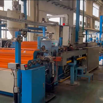
1Insulation Wire Process
Insulating wire is the basic process in the production of digital cables. Designing and controlling the parameters of the insulated single wire is the primary condition.
According to the design, it is generally required that during the production process, the concentricity should be ≥98%, the conductor wire diameter deviation should be limited to 0.002mm, and the insulation wire diameter deviation should be limited to 0.004mm. If the single-wire insulation is physically foamed, the water capacitance should be controlled between ±2.0pF/m, and the insulation foaming degree is generally selected to be around 30-40%. If it is too large, it is easy to flatten the single wire when twisting, and if it is too small, the effect is not obvious.
There is no special requirement for the elongation of copper wire, but the uniformity of annealing is very high. In production, special attention should be paid to the stability of annealing current to ensure the uniformity and stability of copper wire elongation. When producing single wires with large wire diameters, the stability and roundness of the insulation outer diameter are more difficult to control, and are also parameters that have a great impact on the subsequent production. At this time, the precision and stability of the equipment are particularly important.
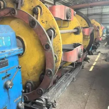
2 Twisting process
The line pair pitch is directly related to whether the crosstalk index of the finished digital cable is qualified or not. There are generally two ways to adjust the pitch of the twisting machine: electronic adjustment and gear adjustment. The electronic pitch change is convenient but has poor stability, while the gear type has good stability. Therefore, it is best to use a twisting machine with a gear type adjustment for production, so that the pitch error can be controlled within ±1%.
In order to reduce the impact of defects in the manufacturing process of insulated single wires on the finished cables, the twisting process is generally produced using a back-twisting twisting machine. The so-called back-twisting is to use the reverse pre-twisting method to reduce or eliminate the self-rotation of the single wire during the manufacturing process. Of course, if the concentricity of the single wire is good, the compensation effect of the back-twisting function will be very small, and then back-twisting will be unnecessary. Moreover, back-twisting will cause certain damage to the single wire. CAT. 6A cable requires a certain amount of back-twisting, and the back-twisting rate is generally selected as 30% to 50%.
When twisted pairs are produced, special precautions must be taken to prevent the two single wires from being squeezed and deformed at the twisting point. The pay-off tension of the two single wires must be consistent, and the phenomenon of one single wire being wrapped around another single wire must be strictly prevented. The pitch of the twisted pair is generally selected between 8.5 and 18.5 mm. Of course, some manufacturers use a smaller pitch to ensure that the crosstalk attenuation and return loss indicators are stable and qualified. This is not objectionable, but attention should be paid to whether the two indicators of phase delay and delay difference are qualified.
3 Cabling process
The purpose of cabling backtwist is to prevent the core wire from being twisted, which may change the structure of the twisted pair wires and affect the performance indicators. The twisted pair pitch and shielding of the twisted pair wires will not change during cabling. Therefore, cabling backtwist of CAT. 6A cables is an effective means to improve the transmission performance of cables. Cabling should use an active pay-off device with tension feedback control to ensure the consistency of the tension of the twisted pair wires over the entire cable length. And ensure that the reverse tension of the four pairs of wires is constant and consistent to ensure good geometric performance of the cable and keep its pitch stable.
The cabling pitch also has a great influence on the cable crosstalk, attenuation and impedance performance. If the pitch is too small, the above electrical performance will fail to meet the standards. The appropriate cabling pitch should be selected through careful calculation and repeated tests, and is generally controlled at 80-120mm.
Shielding method selection
CAT.6A shielded cable generally adopts single-sided aluminum-plastic composite tape, and there are generally two ways: oblique wrapping and longitudinal wrapping: one is oblique wrapping of aluminum foil on the cable (the so-called oblique wrapping is the way of wrapping aluminum foil when forming pitches through cabling), and the other is longitudinal wrapping when sheathing. From the appearance of the finished cable, the oblique wrapping should be tight, and the outer diameter of the entire finished cable should be relatively small; we have tested, using the same process and the same materials, and adopting different wrapping methods for the shielding aluminum foil. From the finished product test data, the overall attenuation index and impedance fluctuation range of the longitudinal sheath are better than the oblique wrapping method, but the oblique wrapping is easy to produce, with high production efficiency and high yield rate. If necessary, the single wire diameter can be thickened to solve the problem.
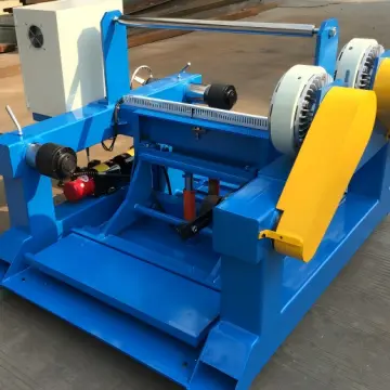
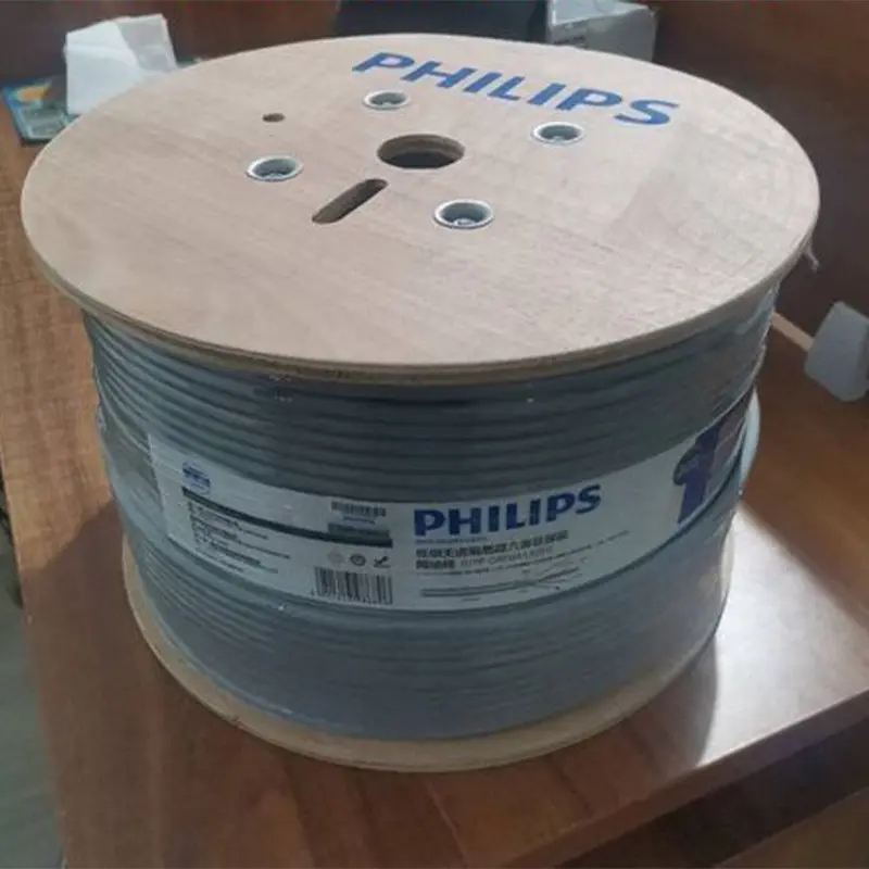
Sheathing and tray loading process
The sheathing process in the manufacturing process is not only about the quality of the sheath appearance, but also about the electrical performance of the finished product. The tightness of the sheath must be well controlled, not too loose or too tight. Too loose will cause the cable structure to be unstable, and too tight will squeeze the wire pairs, causing the relative dielectric constant of the insulation to increase. In particular, it is necessary to adjust the tension of traction and coiling, and try to avoid deformation of the cable core. Once the tension is too large, the electrical properties such as impedance, echo and attenuation will be unqualified, and severe crosstalk will also be affected.
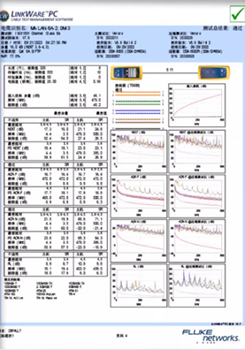
CAT.6A cables are generally required to be reeled when they are finished. The shielding layer is easily twisted due to the small inner hole and severe cable cross extrusion. The twisted impedance will be affected and will lead to failure. Reeling will greatly improve the performance of the entire cable, but it must be noted that when designing the reel, the diameter of the cylinder should be as large as possible. In the process of reeling, the tension of the wire should be reduced as much as possible, which will help improve the impedance and attenuation electrical performance. If the tension is too large, the impedance will appear spikes on the test graph, and the attenuation will appear sawtooth, resulting in failure.
Market prospects of CAT.6A digital cables
The high-end market prospects of the wire and cable industry are broad and worth looking forward to. Wire and cable companies still need to work hard to improve their internal strength and cultivate in depth, and optimize and upgrade their product structure through continuous technological progress. According to the current development trend of the wiring system, we can predict that the wiring market will gradually be replaced by high-end CAT . 6A and even CAT.7 cables, and will sooner or later transition to the 10 Gigabit Ethernet CAT.7 wiring system. Regardless of whether the original installation is a Category 5e system or a Category 6 system, new solutions will inevitably become popular: either a CAT. 6A 10 Gigabit system or a CAT.7 system . However, there are currently module problems based on CAT.7 cables, so the 6A wiring system will definitely be a new highlight and focus.
description2