

Continuous production process of longitudinal welding of copper tape for mineral insulated cables
This paper mainly introduces the equipment and technology of the copper strip longitudinal welding continuous production line, which solves the problem of short cable length, shortens the production cycle, reduces costs and improves production efficiency. It also introduces the difference between rolling and drawing in the manufacture of mineral insulated cables.
1. Overview
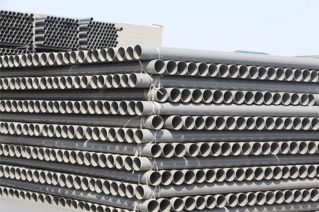
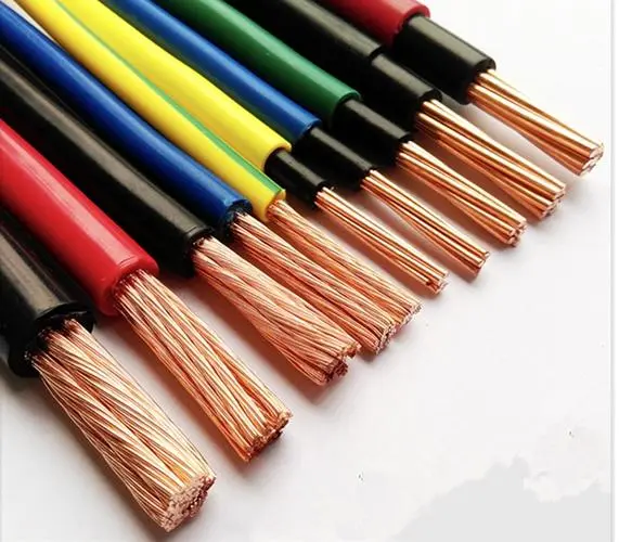
Mineral insulated cable (MI) cable is also called magnesium oxide insulated cable, which is a kind of inorganic material cable. Mineral insulated cable is made of three inorganic materials: copper conductor, inorganic insulating material (magnesium oxide powder) and seamless copper tube or seamless copper tube welded by copper strip longitudinally wrapped, which are processed by multiple drawing or multiple rolling. This unique structure makes it fire-resistant, explosion-proof, high temperature resistant, non-aging, non-causing fire and non-spreading fire, and does not release any harmful gas and smoke under surrounding fire conditions. It is particularly suitable for places or parts with harsh environments and particularly high safety requirements, especially for fire protection system lines that need to ensure safe power supply under fire conditions. When special needs are needed, a layer of polyethylene outer sheath or low-smoke halogen-free sheath can also be extruded on the metal sheath.
Mineral insulated cables can be divided into: wiring cables, heating cables and heating elements, thermocouple cables and compensation cables, special cables according to their uses. The most commonly used in practical applications are wiring cables. The national standard for mineral insulated cables is GB/T13033.1-2007. In addition to the national standard, a new type of mineral insulated special cable has appeared-825 alloy sheathed mineral insulated fireproof cable. 825 alloy sheathed mineral insulated fireproof cable is designed for normal operation (power transmission) in hydrocarbon explosion flames and highly corrosive environments. The cable consists of one or more conductor cores, magnesium oxide powder, and 825 alloy sheath. The conductor core is generally nickel-clad copper or pure nickel solid core. The outer sheath of 825 alloy cable cannot be used as a grounding wire. 825 alloy has acid and alkali metal corrosion resistance in both oxidizing and reducing environments, and the high nickel content makes the alloy effectively resistant to stress corrosion cracking. It has good corrosion resistance in various media, such as sulfuric acid, phosphoric acid, nitric acid and organic acids, alkali metals such as sodium hydroxide, potassium hydroxide and hydrochloric acid solution. Alloy 825 is the only alloy found so far that has excellent all-round performance in environments where organic sulfides, hydrogen sulfide and sulfur combustible products are produced at high temperatures (such as petroleum and petrochemical plants). The mineral insulated fireproof cable with 825 alloy sheath can not only survive in a high-temperature explosion flame of 1200℃ for 30 minutes, but also has strong corrosion resistance to petroleum gas and acid mist. The test was conducted by Exxon-Mobil Oil Company, which placed the 825 alloy cable in an environment very similar to an actual hydrocarbon flash fire. The test procedure stipulates that the tested cable must be supported in a furnace pit filled with a mixture of gasoline and diesel. When this mixture is ignited, the temperature in the furnace rises sharply and burns violently. In the test, the tested cable sample not only withstands the high temperature of the flame, but also the destructive turbulent fire. During the entire test, the average temperature exceeded 1100℃. Due to the characteristics of the test itself, the temperature fluctuated up and down at the 1100℃ level. The test shows that the cable can continue to work normally under fire conditions.
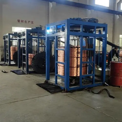
2. Equipment diagram
2.1 Double copper strip pay-off device:
Construction: The double copper belt pay-off device is a pay-off machine with 2 independent pay-off rods and air brakes. The two independent pay-off rods can rotate, and the pay-off diameter of each rod is within (240-470) mm. The maximum belt width is 320 mm, and the length of the 4 supporting bars next to it is 600 mm each. The maximum weight of the copper belt is (total) = 1400 kg, and 60.5 mm wide copper belt is generally used (the maximum weight of each reel can reach 700 kg).
Function: Keep a certain tension between the copper strip pay-off machine and the copper strip storage device. The advantage of the copper strip pay-off machine is that when a copper strip is used up, another copper strip can be replaced and welded with it without stopping the machine (argon gas is used as the protective gas, and UTP silver electrode is filled with argon arc welding), ensuring continuous production of the production line.
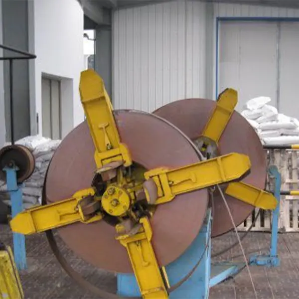
(Double copper tape pay-off device)
2.2 Copper tape storage device:
Construction: The copper belt storage pulley is 4 meters high and 2.5 meters wide. There are vertical columns on both sides, and a pulley block (6 pulleys with a diameter of 360 mm) at the top. There is another pulley block in the middle (5 pulleys with a diameter of 360 mm). The pulley block is not electrically driven but has a hydraulic tension control unit that can stop it in case the copper belt breaks. (As a protective measure) A single pulley fixed in a fixed safety cage guides the copper belt into the pulley block. There is also a signal device to determine the position of these pulleys.
Function: To ensure that the copper strip in the copper strip storage device and the copper strip cleaning machine have a certain tension. The copper strip storage device can store enough copper strips to gain sufficient time for welding between copper strips.
(Copper tape storage device) (Picture omitted)
2.3 Copper belt cleaning machine
Structure: The copper belt cleaning machine is about 2.5 meters long, 1.2 meters high and 0.6 meters wide. The main parts of the shell are made of acid-resistant plastic. It has a system to control the copper content and a system to control the temperature of the cleaning liquid. There are two motors for circulating tap water and cleaning liquid. The inlet and outlet width is 100mm. The built-in conveyor belt is up to 64mm wide.
Function: 10%-15% dilute sulfuric acid and 10%-20% hydrogen peroxide are used to pickle the surface of the copper strip to remove oil, deoxidation and other chemical reactions. The pickled copper strip is then washed with water, and finally dried at no less than 35 degrees before being transferred to the copper strip forming mill.
(Copper belt cleaning machine) (Picture omitted)
2.4 Copper strip forming mill
Construction: A copper strip forming machine with 13 universal joints, 7 power-guided dies, 2 motors, 7 gearboxes and 7 rollers (each in pairs), the remaining 6 unused ones are all fixed to the main frame. The first three gearboxes are connected together and driven by the motor next to the first gearbox. The last four gearboxes are connected together and driven by the motor next to the 7th gearbox. The rollers are connected to the gearbox that sends out the rolling shaft. When the copper strip tube is formed and rolled, all these rollers must work concentrically and vertically. The motor, gearbox and rollers are also the same. The gear ratio of each ring is the same 79:1 (gearbox and wheels) Motor information: Universal motor, 1000 rpm, 3.8 kW DC split-excitation motor. Armature = 180 volts, 28.5 amps. Field voltage 210 volts, 1.95 amps. The motor uses a fan to cool it.
Function: The 60.55 mm wide copper strip is longitudinally wrapped into a 19.8 mm copper tube. The gap between the longitudinally wrapped seams is about 0.1 mm to facilitate welding.
(Copper strip forming mill)
2.5 Welding system
Construction: Welding box with 3 pairs of water-cooled rollers with a diameter of 20 mm. Silicone oil delivery system consisting of a "Watson Marlow" 504 DU pump, a spherical sensor with a viewing hole, and a rack for silicone oil drums. Vibrating hammer consisting of: a DC motor and a gearbox in a cam mechanism. Motor control panel consisting of: a Lincoln welding machine, a separate high-frequency 400 amp power supply and welding gun, with circulating condensed water for cooling. Seam control panel with camera, touch welding monitor.
Function: The most important part of the continuous production process of copper strip longitudinal welding is to ensure the quality and stability of welding. The seams of the copper strip into tubes are automatically tracked by the camera and automatically adjusted for welding, ensuring the stability and quality of welding.
(Welding device - picture omitted)
2.6 No. 1 rolling mill
Construction: Mill 1 consists of 7 motors. Its gear ratios vary according to the gearbox and the motor drive pulley. All roll stands are mounted on the main structure. The roll stands are at right angles to each other. The motors, gearboxes, and rolling places of all roll stands are the same. Each roll stand has a DC motor driving a belt to the gearbox. Until the rolling place. Motor information: "Universal Motor" 3000 rpm, 2.2 kW DC split-excitation motor. Armature voltage = 180 volts, 13.5 amps. Field voltage 210 volts, 0.78 amps. Motor structure = MD132160 (with footrest). Control system: Control is all connected to the main line control system. Local control is done by microcontroller on the main control desk on the first floor.
Function: The combined copper wire core, magnesium oxide and copper strip are rolled into semi-finished products after multiple times. The cable diameter sent out by roller No. 1 is 19.07mm, and the cable diameter sent out by roller No. 7 is 15.52mm. (Figure omitted)
2.7 Annealing device No. 1, cooling water tank and guide wheel, rolling mill No. 2 and No. 3
Structure (Annealing Device No. 1): 125 kW 10,000 Hz water-cooled motor, coil box and water circulation system, coil diameter 30 mm, glass pad tube outer diameter 26 mm, inner diameter 20 mm, length 1650 mm. Function (Annealing Device No. 1): High current induction heating cable. Heating principle: 50HZ industrial frequency current is converted into 10KHZ AC power supply, using a thyristor frequency conversion device, conductive materials are induced in the magnetic field, the material itself generates eddy current and hysteresis loss, causing the material itself to heat up, a physical phenomenon.
Construction (Cooling water tank (quenching) and pulley): 3350mm x 610mm x 1600 mm (depth height) cooling water tank with guide pulley. Pulley enables vertical movement, 1800mm aluminum pulley, limit switch and LVDT. The water tank is connected to the circulation pump and heat exchanger by the water pump. Function (Cooling water tank (quenching) and pulley): Designed to solve three problems in the mineral cable production process. 1) Change the cable from a tree to a horizontal one 2) Cool the cable coming out of the No. 1 annealing device 3) Provide signal position for the rolling speed control circuit of the No. 2 rolling mill.
Construction (Mill 2): Mill 2 consists of 12 motors: All roll stands are mounted on the main structure. Roll stands are at right angles to each other. All roll motors, gearboxes, and rolling areas are the same. The gear ratios of each roll are different depending on the gearbox and the drive pulley of the motor. Motor information: Universal motor 3000 rpm, 2.2 kW DC split-excitation motor. Armature voltage 180 volts, 13.5 amps. Field voltage = 210 volts, 0.78 amps. Full control system: The control unit is connected to the main line control system.
Function: The cable diameter sent out by roller No. 1 is 15.07mm, and the cable diameter sent out by roller No. 12 is 7.88mm. Structure: (The principle of roller No. 3 is the same as that of roller No. 2)
Function: The cable diameter sent out by the No. 1 roller of the No. 3 rolling mill is 9.96mm, and the cable diameter sent out by the No. 12 roller is 5.15mm. (All pictures omitted)
2.8 Annealing device No. 2, laser diameter gauge, eddy current tester
Structure (Annealing Unit No. 2): 250 kW, 10,000 Hz water-cooled motor, including six coil boxes with an inner diameter of 30 mm and a length of 4270 mm, water cooling system, etc. Glass pad tube outer diameter 24.5 mm, inner diameter 19.5 mm (700 mm long). Function (Annealing Unit No. 2): (Same as Annealing Furnace No. 1, Figure omitted) Structure (Laser Diameter Gauge): Equipped with laser measuring head. The system has an alarm box Function (Laser Diameter Gauge): Detect whether the outer diameter of the cable is within the range of ±0.5 mm.
Structure (eddy current tester): equipped with flaw detection (poor welds) laser head and display instrument screen.
Function (eddy current tester): detect bad welds and alarm, and the air pressure device equipped with a black punch will punch a black mark to remind the wire take-up personnel to separate the wires. (Figure omitted) 2.9 Downward coil take-up device
Construction: It consists of an upper tray with V-grooves and a lower turntable. The diameter of the turntable is 1000mm, and the "fingers" and "feed roll" are controlled by pneumatic pistons. The turntable has a diameter of 1160mm and is driven by a chain.
Function: To coil the wire and ensure the replacement of the wire reel during continuous production.
(Wire-receiving device - picture omitted)
3. Materials
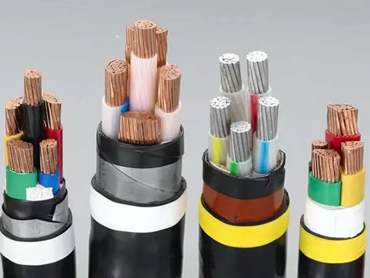
3.1 Conductor structure diagram (omitted)
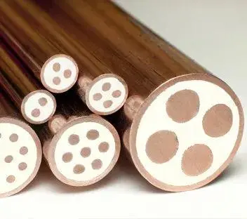
The typical structure of mineral insulated cable is shown in the figure on the right. The conductor, magnesium oxide and sheath are rolled together many times, and the three are highly compressed and the density of magnesium oxide is very high. If the cable is required to have corrosion resistance, an outer sheath can be extruded outside the copper sheath. Under normal circumstances, an outer sheath is extruded. Under normal circumstances, the conductor and sheath are made of copper material and the insulation layer is made of magnesium oxide material.
The conductor size specifications of wiring cables are quite varied, ranging from 1mm2 to 400mm2, and the number of cores also ranges from 1 to 19. Generally, only the conductor cross-section of single-core cables is greater than 25mm2, and the conductor cross-section of multi-core cables with 7 cores, 12 cores, and 19 cores is generally smaller. 2, 3, 4, and 7-core cables are shown in the figure on the right (omitted).
3.2 Material Introduction
The raw materials used in the continuous production process of copper strip longitudinal wrap welding are phosphorus-containing oxygen-free copper strip, magnesium oxide powder with silicone oil, and coiled copper conductor. The phosphorus-containing oxygen-free copper strip can weigh up to 700kg, and the coiled copper conductor can weigh up to 1 ton. However, a cable in the filling or porcelain column assembly process can only reach about 200kg, so from the source, the continuous production process guarantees the supply length of raw materials. In theory, during the production process of the continuous production process of copper strip, the quality of raw materials is guaranteed and the electrical stability is high. A 2L1.5 cable can reach about 8 kilometers. Due to the constraints of the take-up device, a 2L1.5 cable can also be up to about 4 kilometers.
3.2.1 Conductor materials
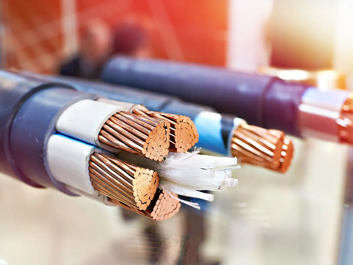
The conductor material used in mineral insulated cables is solid, annealed, high-conductivity oxygen-free copper with a nearly circular cross-section. The two necessary conditions for conductor materials are high conductivity, which is the most basic for the effective transmission of electrical energy, and the extensibility of the material to meet the process requirements. Flexible copper with high conductivity can meet the requirements of most wiring cable conductors. The oxygen content in oxygen-free copper is very low, and the structure of this copper is a uniform single-phase structure, which is very beneficial to toughness. The rollability of oxygen-free copper is superior to that of low-oxygen copper rods in all wire diameters.
3.2.2 Sheath material
The standard sheath raw material is phosphorus-containing deoxidized copper strip (phosphorus-containing copper strip is easy to weld). The deoxidized phosphorus copper strip does not contain arsenic, the tellurium content does not exceed 50ppm, and the sulfur content does not exceed 15ppm. The edges and corners of the phosphorus-containing deoxidized copper strip must be smooth, clean, bright, burr-free, and oil-free to ensure the stability and quality of welding and the smooth progress of rolling.
3.2.3 Insulation materials
The inorganic magnesium oxide used as the insulation material of mineral insulated cables has very stable physical and chemical properties, no corrosion to copper, a melting point of up to 2800°C, high electrical strength, high thermal conductivity, and is non-toxic. The purity of the material can be as high as 94% or more. For special occasions such as nuclear power plants, the purity of magnesium oxide is required to be higher. The magnesium oxide used in the continuous production process of copper strip longitudinal welding mainly considers three aspects: flow rate, density, and particle size distribution of magnesium oxide.
- The flow rate is controlled between 160∽210s/100g.
- The tap density is between 2.13 and 2.33 g/cm3.
3) Particle size distribution is directly related to density. The normal particle size distribution is from +40-325 mesh, and it decreases from high to low.
3.2.3.1 Electrical properties of magnesium oxide:
Checking the physical and chemical indicators of magnesium oxide powder has only one fundamental purpose, which is to ensure good electrical performance indicators. Electrical performance indicators are divided into normal state, hot state and wet state.
Normal test refers to measuring the insulation resistance and withstand voltage of the pipe after it is manufactured under normal circumstances, which is called normal insulation and normal withstand voltage.
The hot test is to turn on the power under various set conditions, and observe the leakage current, resistance and withstand voltage of the tube under certain load conditions. In fact, these data are used to evaluate the quality of magnesium powder.
The tidal test is to put the pipe with or without electricity into a constant temperature and humidity chamber (humidity chamber) for a certain period of time to observe the moisture absorption performance of magnesium oxide. Generally, it is placed at 42℃ or 50℃ for 48 or 72 hours before measuring the insulation and withstand voltage of the pipe (representing the insulation and withstand voltage of magnesium oxide).
Continuous production process of longitudinal welding of copper strips for mineral insulated cables
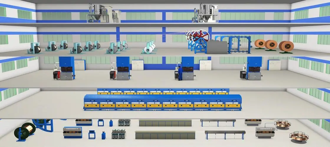
The production process flow chart is shown below: (omitted)
The copper strip longitudinal welding continuous production line consists of two parts, vertical and horizontal. The vertical part includes two inclined cylinders and hoppers for adding magnesium oxide powder, tube forming rollers on the third floor, cleaning machines, welding heads, circulating water condensing compressors, pressure wheels, and No. 1 rolling mill on the second floor. The horizontal part includes No. 1 annealing induction annealing box, two quenching cooling water tanks, three rolling mills, No. 2 annealing induction annealing box, outer diameter detector, eddy current tester, and wire take-up device on the first floor.
First, insert the 0.95mm (thickness) * 60.55mm (width) copper strip (this is only one specification) on the copper strip pay-off device into the copper strip storage device, wash it with water, pickle it with a copper strip cleaning machine, and dry it at no less than 35°C, and then pass through the forming wheel of the forming mill to continuously wrap it into a cylindrical shape. At the welding water-cooled roller, the edges of the copper strip are aligned and close to each other, and the gap between the seams is about 0.1 mm. Electrode rods are used for argon arc welding (no need to fill solder or argon as a protective gas). The welding head is at an angle of 110 degrees to the center of the sheath to preheat the edge of the copper strip. The copper strip welding speed is 1.0-3.0m/min, the welding current is about 205-270A, and the welding voltage is about 12-13V. Pay close attention to the surface quality of the copper sheath after welding, and the surface of the copper strip is fish-shaped. There should be no undesirable phenomena such as leakage, holes, and dripping.
Secondly, according to the process requirements, select a suitable stainless steel core tube, and put it from the lower mouth of the magnesium oxide powder hopper to the space between the forming mill and the No. 1 rolling mill. At this time, insert the silicone oil conduit into the core tube. The function of the core tube is mainly to ensure that the insulation thickness between the wire core and the copper sheath and between the wire cores is uniform, and it is fixed to the lower bracket of the magnesium oxide powder hopper, and connected with the hopper and the powder inlet on the core tube with a "trumpet" type rubber sleeve, and the upper and lower openings are tightened and sealed with stainless steel pipe clamps. In order to ensure that the conductive wire core is not eccentric in the copper sheath, the lead wire is inserted into the core tube through the sizing die, and then the lead wire and the conductor wire core are welded together. At this time, the sizing die should be placed in the die sleeve and fixed on the magnesium oxide powder funnel bracket. The sizing die hole is required to be in a straight line with the core tube of the wire core (the diameter of the sizing zone of the sizing die is about 0.1-0.6mm smaller than the diameter of the copper wire core blank, and it mainly plays the role of sizing, straightening, and removing impurities on the surface of the conductor).
Then, the lead wire is passed under the seventh roller of the No. 1 rolling mill, and the magnesium oxide powder is poured into the copper sheath from the funnel. In order to ensure the smooth filling of magnesium oxide powder and the density of magnesium oxide powder in the copper sheath, a pair of small hammers are placed between the welding gun and the copper tube sizing wheel to knock the copper tube at a certain frequency (the frequency is about 20-80 times/minute). The amount of magnesium oxide powder supplied in the funnel can be controlled by the powder level sensor signal in the funnel and the inclined cylinder. Both the funnel and the inclined cylinder have sensors. Once the magnesium oxide powder leaves the sensor probe, an alarm will sound.
The semi-finished product is continuously rolled and annealed in the middle (twice) by the rolling mill to obtain the required finished cable diameter. Each rolling mill stand is equipped with several pairs of rollers to compact the magnesium oxide powder insulation and reduce the cable diameter. After rolling, the cable is annealed in the middle (capacity 50-110 kW) and quenched in a circulating cooling water tank with alcohol added.
The speed of the entire production line is set by the main console according to the process parameters, and the power of the annealing furnace can be controlled manually. In the normal production process, intermediate inspections must be carried out continuously to check whether the motor speed is overloaded and a series of other tasks.
5. Technical data (province)
This section mainly introduces the technical requirements for raw materials, auxiliary materials, accessories, process control, quality analysis, etc.
6. Rolling and drawing
6.1 History of Rolling Mill Development
A rolling mill is a device that realizes the metal rolling process. The earliest record is the sketch of a rolling mill designed by Italian Leonardo da Vinci in 1480. In 1553, Frenchman Brussels rolled gold and silver plates to make coins. After that, rolling mills appeared in Spain, Belgium and Britain. In 1728, Britain designed a rolling mill for producing round bars. In 1766, Britain had a serial small rolling mill. In the middle of the 19th century, the first reversible plate rolling mill was put into production in Britain and rolled out iron plates for ships. In 1848, Germany invented the universal rolling mill, and built the first continuous rolling mill in 1859. The universal profile rolling mill appeared in 1872. In the early 20th century, a semi-continuous strip steel rolling mill was made, consisting of two three-roller roughing mills and five four-roller finishing mills.
6.2 Rolling Principle of Rolling Mill
At present, the main equipment of our company's rolling mill is the 14-stand rolling mill from the German company Bohler and the 7-stand and 12-stand rolling mill from the British company KANTHAL. The rolling principle of the mineral insulated cable rolling mill: through the drive of the gear set on the transmission shaft of the DC motor, the movement of the two universal joints connected to the gear set will drive the paired rollers connected to the universal joints, thereby achieving the purpose of rolling. The surface phenomenon of the rolling mill principle is very simple. The cable or copper conductor with a larger outer diameter passes through the roller groove of a pair of rotating rollers. Due to the compression of the rollers, the material cross-section is reduced and the length is increased. At present, our company directly rolls the semi-finished cable of ¢24.5 mm into the data specified by the process parameters. At present, the largest roller of the rolling mill can roll ¢32 mm cable, and the ¢32 mm cable can be directly rolled to ¢5.15 mm. The control system of the rolling mill is relatively complex, which is generally divided into three parts: mechanical, hydraulic and electrical control. The accuracy of the rolling mill is not only related to the level of mechanical manufacturing, but also hydraulic and electrical control are necessary.
6.3 Rolling Mill Equipment Structure
The rolling mill mainly consists of a working machine base and a transmission device. The working machine base consists of rollers, roller bearings, frames, rail seats, roller adjustment devices, etc. Rollers are components that cause metals to deform plastically. Working machine base: 1) Roller bearings support the rollers and keep the rollers in a fixed position in the frame. 2) Rolling mill rail seats: used to install the frame and fixed on the foundation, also known as the foot plate. They bear the gravity and tipping moment of the working machine base, while ensuring the accuracy of the installation size of the working machine base. 3) Roller adjustment device: At present, the roll gap of the 14-stand rolling mill of the German Böhler Company does not need to be adjusted. The rolls are automatically replaced according to the parameters pre-set by the main control console. It only takes about 2 minutes to change the rolls once. However, it is very troublesome to replace the rolls of the 7-stand and 12-stand rolling mills of the British KANTHAL Company. The roll gap needs to be adjusted to replace the rolls. It normally takes several hours to replace the rolls once. Transmission device: It consists of a DC motor, a universal joint, a gear seat and a connecting shaft. The gear seat distributes the transmission torque to the two rolls.
6.4 Drawing principle
The principle of drawing: a processing method in which the metal billet passing through the drawing die hole is clamped by the jaws of the drawing machine and pulled out from the die hole to obtain a product with the same cross-sectional shape and size as the die hole. Unlike the extrusion and rolling processes, the drawing process is achieved by applying a tensile force to the front end of the metal being processed. This tensile force is the drawing force. The ratio of the drawing force to the cross-sectional area of the pulled metal at the die outlet is called the unit drawing force, that is, the drawing stress. In fact, the drawing stress is the longitudinal stress at the end of the deformation zone, and the drawing stress should be less than the yield strength of the metal outlet die. If the drawing stress is too large and exceeds the yield strength of the metal outlet die, it may cause the product to have a thin neck or even break. Therefore, the drawing stress should be less than the deformation tension after the metal exits the die.
6.5 Rolling and drawing technical data
Rolling: ¢24.5 mm ¢10.7 mm
|
frame |
Roller groove Roller groove |
Large diameter |
Small diameter |
Cross-sectional area |
oval |
Section compression rate |
Elongation |
speed |
Roller speed |
Cable Rate |
|
Input |
|
24.50 |
24.50 |
471.44 |
0.00 |
|
|
2.05 |
|
|
|
1 |
1 |
24.52 |
21.54 |
414.82 |
12.15 |
12.01 |
13.65 |
2.33 |
4.90 |
1.00 |
|
2 |
1 |
21.56 |
21.56 |
365.08 |
0.00 |
11.99 |
13.62 |
2.64 |
5.57 |
1.14 |
|
3 |
1 |
21.58 |
18.96 |
321.35 |
12.14 |
11.98 |
13.61 |
3.00 |
6.33 |
1.29 |
|
4 |
1 |
18.98 |
18.98 |
282.93 |
0.00 |
11.96 |
13.58 |
3.41 |
7.19 |
1.47 |
|
5 |
1 |
19.00 |
16.87 |
251.74 |
11.21 |
11.02 |
12.39 |
3.83 |
8.17 |
1.67 |
|
6 |
1 |
16.89 |
16.89 |
224.05 |
0.00 |
11.00 |
12.36 |
4.30 |
9.18 |
1.87 |
|
7 |
1 |
16.91 |
15.02 |
199.48 |
11.18 |
10.97 |
12.32 |
4.83 |
10.31 |
2.10 |
|
8 |
1 |
15.04 |
15.04 |
177.66 |
0.00 |
10.94 |
12.28 |
5.43 |
11.58 |
2.36 |
|
9 |
1 |
15.06 |
13.14 |
155.42 |
12.75 |
12.52 |
14.31 |
6.21 |
13.01 |
2.65 |
|
10 |
1 |
13.16 |
13.16 |
136.02 |
0.00 |
12.48 |
14.26 |
7.09 |
14.87 |
3.03 |
|
11 |
1 |
13.18 |
11.56 |
119.66 |
12.29 |
12.02 |
13.67 |
8.06 |
16.99 |
3.47 |
|
12 |
1 |
11.58 |
11.58 |
105.32 |
0.00 |
11.99 |
13.62 |
9.16 |
19.31 |
3.94 |
|
13 |
3 |
11.60 |
10.65 |
97.03 |
8.19 |
7.87 |
8.54 |
9.94 |
21.94 |
4.48 |
|
14 |
3 |
10.67 |
10.67 |
89.42 |
0.00 |
7.84 |
8.51 |
10.79 |
23.81 |
4.86 |