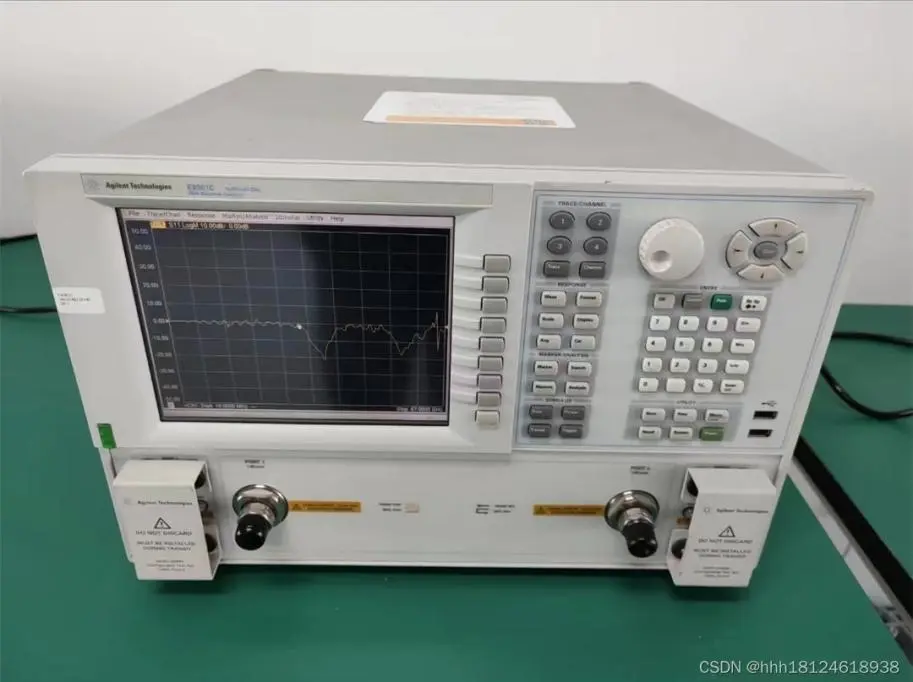
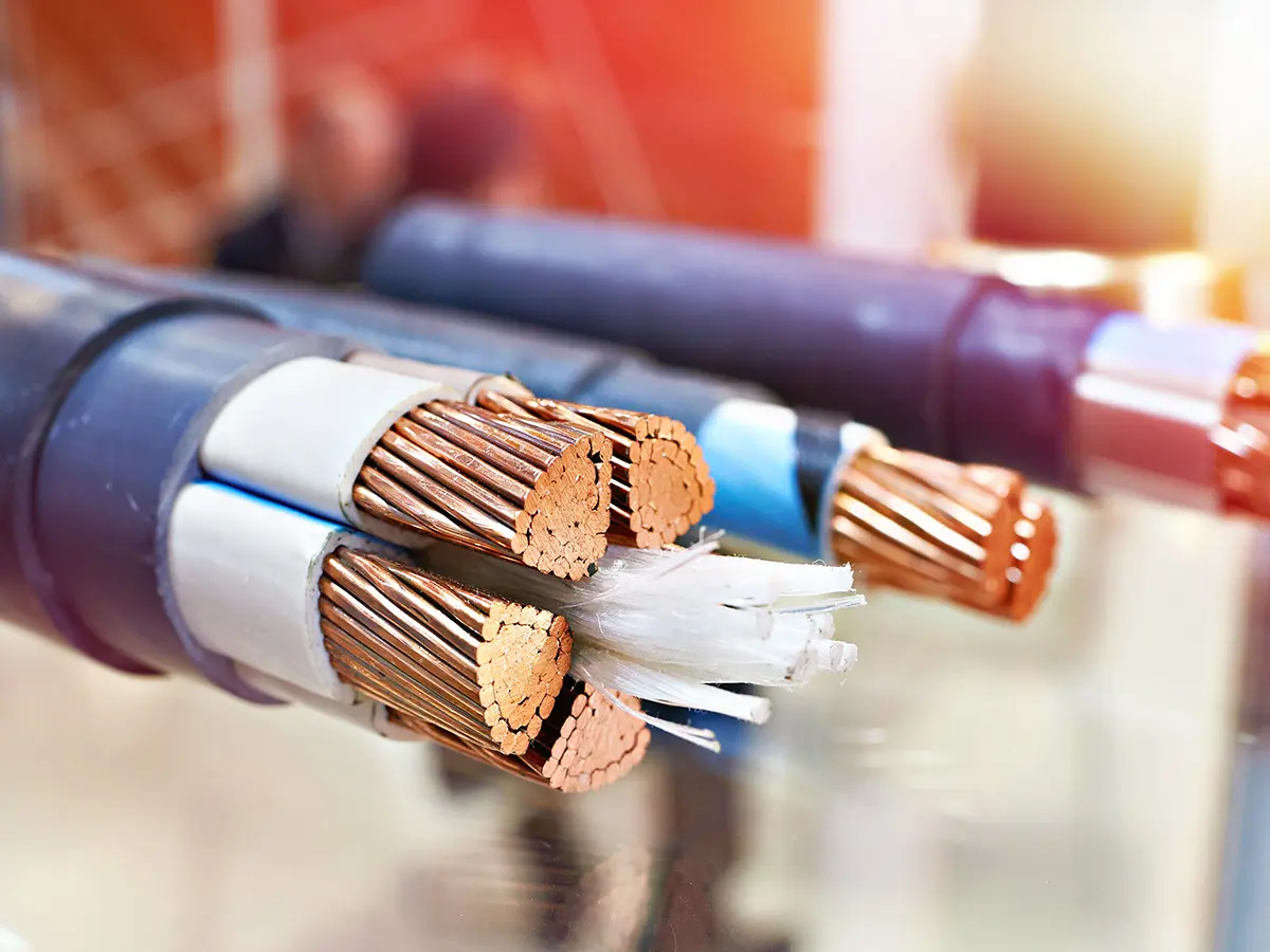
5G digital communication Cat.7A/8 cable production process
1. As the fifth generation of mobile communication network, the peak theoretical transmission rate of 5G network can reach 10Gbps per second, which is hundreds of times faster than the transmission speed of 4G network. With the increase of 5G transmission rate, the frequency and transmission rate requirements of digital communication cables are getting higher and higher. Category 7 digital communication cables (maximum transmission frequency up to 1000MHz, transmission rate 10Gbps) and category 8 digital communication cables (maximum transmission frequency up to 2000MHz, transmission rate 40Gbps) can well meet the construction of 5G communication network infrastructure.
2. Therefore, a comprehensive analysis of the key points of process control for producing Category 7 and Category 8 digital communication cables that meet the standards is conducted, which will play a certain guiding role in improving and ensuring the manufacturing accuracy, stability and uniformity of Category 7 and Category 8 digital communication cables.
Keywords:Skin-foam-skin physical foaming; digital communication cable.
Preface
3. At present, digital communication cables have been widely used. The maximum transmission frequency of Category 7 can reach 600MHz; the maximum transmission frequency of Category 7e (7A) is 1000MHz and the transmission rate is 10Gbps; Category 8 digital communication cables can meet the requirements of transmission frequency 2000MHz and transmission rate 40Gbps.
4. In the near future, 5G technology will be widely used and developed, and the demand for Category 7 and Category 8 digital communication cables will continue to increase, with good development prospects. In order to ensure that Category 7 and Category 8 digital communication cables meet the corresponding bandwidth and transmission rate, production process control is very important, and any production link should be strictly controlled.
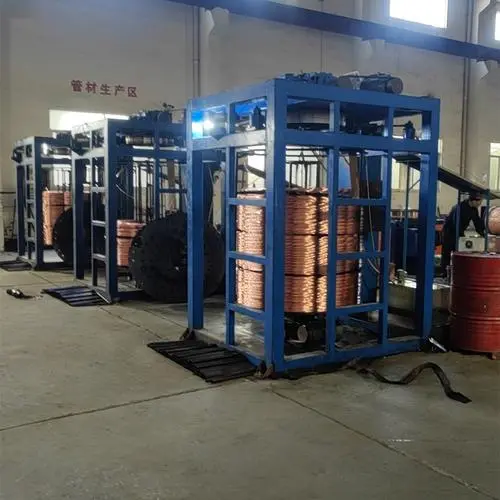
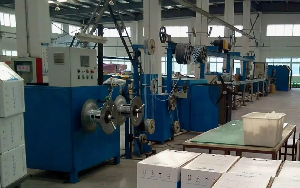
1. Copper wire conductor drawing and annealing process control
1.1 Conductor wire drawing process control
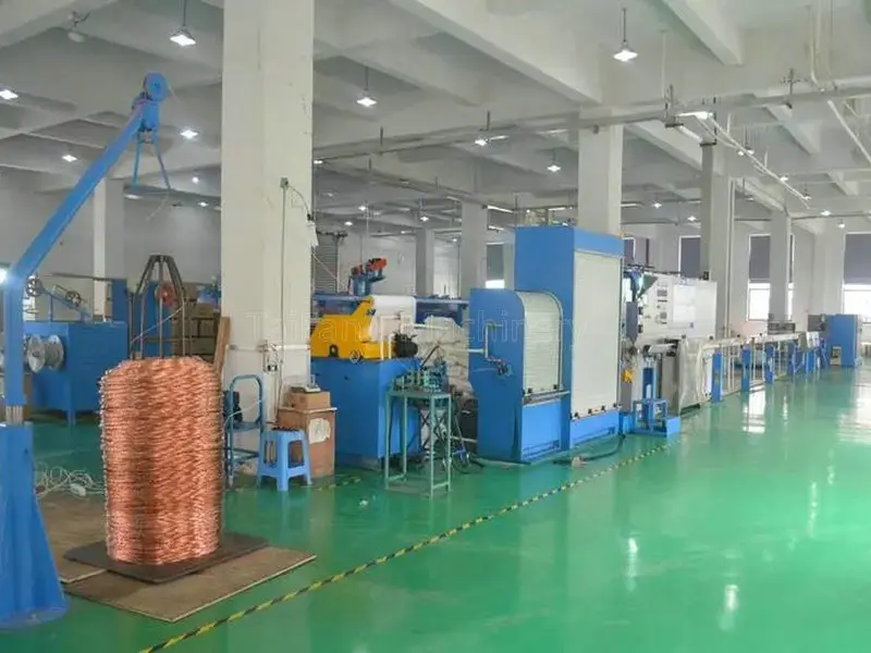
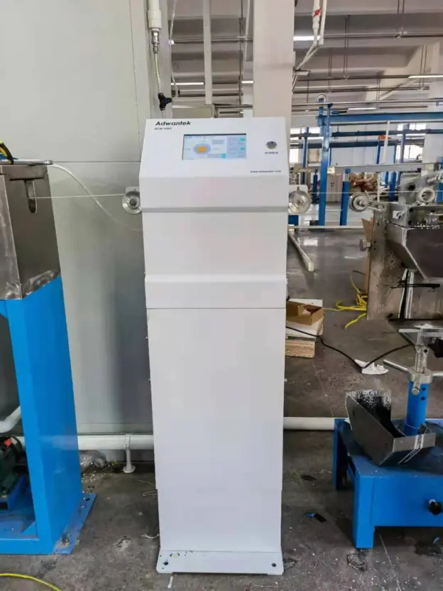
- The resistance coefficient of the copper wire conductor should not be significantly different, the annealing should be balanced, the deviation of the elongation at break should be controlled at about ±2%, the conductor diameter tolerance should be limited to ±0.002 mm, and the copper wire must be round and smooth. , no oxidation spots, and a small wire diameter deviation range. It is recommended to use a "drawing--annealing--conductor preheating--extrusion" series production line. The wire drawing, annealing, preheating, and extrusion production processes can be completed at one time, reducing the damage to the conductor caused by multi-link production in the intermediate links, and ensuring the stability of the conductor's wire diameter and softness.
- When drawing copper wire, select an appropriate conductor sizing die. Taking into account the stretching of the conductor during subsequent processing, select an appropriate sizing die based on the accuracy of the production equipment of different manufacturers. In the drawing process, the copper rod is drawn to the required size through the die hole of the drawing die using a drawing machine at normal temperature. The main parameter is the die matching technology. The emulsion concentration is controlled at about 8% to 10%, and the temperature is controlled at 35-45℃, the temperature is not easy to be too high, and the pH value is ≥7 or above.
(2) Copper wire annealing and preheating control
- Copper wire annealing, by controlling the annealing voltage to control the current to heat the copper wire to a certain temperature, annealing crystallization can improve the flexibility of the copper wire, reduce the strength of the copper wire, make it not easy to break, have good conductivity, and meet the requirements of the conductive core wire.
- In order to ensure that the copper wire is uniform in hardness and softness, the copper wire and the conductive ring must be in full contact without any shaking;
- The annealing voltage should be set reasonably. If the annealing voltage is too low, no annealing will be achieved. If the annealing voltage is too high, the copper wire surface will turn yellow and slightly oxidized.
- The cooling water temperature in the annealing tank must be strictly controlled and should not be too high. It is recommended to use a cooling water circulation cooling system and replace it regularly to maintain an ideal cooling effect;
- The copper wire cooled by cooling water is blown dry with a blower to ensure that there is no water residue on the surface of the copper wire, so as to ensure that the copper wire is not oxidized and blackened or has spots;
- After the copper wire is annealed and cooled before entering the extruder, it is recommended to apply a certain current to preheat the copper wire to improve the adhesion between the copper wire and the plastic. The preheating temperature fluctuation of the conductor should be small to ensure that the gap between the copper wire and the insulation layer For good bonding, the equivalent dielectric constant of the insulation on the entire single line must be uniform;
- The resistance coefficient of the copper wire should not be significantly different, the annealing should be balanced, the elongation should be controlled within ±1%, the conductor diameter tolerance should be limited to within ±0. 002 mm, and the insulation outer diameter should be limited to within ±0. 01 mm. The coaxial capacitance is limited to ±1. 5 pFPm, the concentricity should be greater than 96%, the conductor preheating temperature fluctuation should be small to ensure good bonding between the copper wire and the insulation layer, and the equivalent dielectric constant of the insulation on the entire single line Must be uniform.
2. Skin-foam-skin-insulated core wire extrusion process control
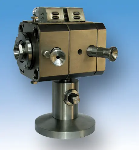
- It is recommended to use the skin-foam-skin physical foaming extrusion process for insulating core wires, and use a three-layer co-extrusion die with high die head precision to ensure product concentricity and extrusion pressure. The extrusion screw plasticization should be good, and it is recommended to use a 1:28 aspect ratio screw. Choose a foaming material with stable foaming, and it is best to use a granular material mixed with a foaming agent and a masterbatch for extrusion. The foaming holes should be uniform, the injection pressure should be stable, the changes in the number of screw revolutions and the tension of the retracting and releasing wires should be as small as possible, and the pores of the foaming layer should be uniform and dense. The design of the mold sleeve should ensure a sufficiently reasonable compression ratio to obtain suitable pores. Generally, an extrusion mold is used. The inner diameter of the mold core should be suitable for passing the core wire and should not be too small, otherwise it will cause the core wire to shake or the conductor surface to be scratched, and the mold itself will also be easily injured; if the inner mold of the mold core is too large, it will cause eccentricity, that is, poor concentricity. The quality of the insulation core wire directly affects the capacitance, insulation performance and crosstalk index. At the same time, the physical foam insulation core wire has the characteristics of small attenuation, small working capacitance, small loss coefficient, small dielectric constant and long transmission distance. Under the condition of equal capacitance, the cable has small diameter, low cost and light weight. Coaxial capacitance is the key to control the electrical parameters of the product. The copper wire diameter, insulation outer diameter, insulation concentricity and foaming degree can be controlled by configuring online monitoring equipment such as outer diameter tester, water capacitance meter and eccentricity meter.
- Compared with traditional insulation production equipment, the skin-to-skin physical foaming production line has many control parameters and complex adjustment. Only by strictly controlling the equipment parameters can the foaming degree, insulation wire diameter, coaxial capacitance, concentricity, ellipticity, etc. be controlled to produce a uniform and stable core wire.
- During extrusion foaming, it is necessary to prevent oxidation of copper wire. When the foaming is too high and the pressure of the foam layer is too large, the polar molecules of the foam layer overflow to the surface of the insulation layer, causing the surface to be rough. Overflowing to the conductor direction causes the inner skin insulation structure on the surface of the copper conductor to rupture. The combination of polar molecules and copper will also cause oxidation of the copper wire. The degree of foaming also directly affects the tensile strength and elongation of the insulation. The increase in the degree of foaming leads to a small elongation of the insulation and a decrease in the mechanical strength. Therefore, a suitable degree of foaming should be selected. Excessive foaming leads to a decrease in coaxial capacitance, a deterioration in the mechanical properties of the product, and it is difficult to achieve the expected design effect; while excessive foaming leads to excessive coaxial capacitance, series connection of the foam wall, and changes in mechanical properties. The adjustment of the degree of foaming must be completed through a comprehensive change in the amount of nitrogen injected, the speed of extrusion, the size of the wire diameter, and the line speed. At the same time, it is recommended to configure a pressurized nitrogen injection system to keep the pressure of the injected nitrogen constant, which is not affected by the reduction of the amount of nitrogen in the nitrogen bottle and the pressure reduction, so as to obtain a stable foaming degree and a stable insulation outer diameter of the insulating core wire.
3. Core wire twisting process control
1. Insulated core wire twist control
- By designing a reasonable twisting pitch for the four pairs of wires and leaving a certain pitch difference between the four pairs of wires, the near-end crosstalk and far-end crosstalk of the cable can be optimized. Detwisting is required when twisting the pairs. Detwisting the twisted pairs can improve the impedance fluctuation caused by the eccentricity of the single wire or the uneven wire diameter, making the transmission performance more stable. Detwisting is actually pre-twisting, that is, before twisting the twisted pairs, a certain twist is given to the single wire in the opposite direction, so that the change curve between the characteristic impedance and the frequency is more gentle. The increase in the detwisting rate can improve the electrical performance.
- However, if the back-twist rate is not designed properly, it will also bring side effects and cause the single-wire structure to be partially destroyed. Therefore, the back-twist rate should be controlled at about 15~20%, preferably not more than 35%, and should be set according to the different performance and accuracy of the equipment of each manufacturer. When twisting the pairs, the extrusion deformation at the contact point of the core wire should be minimized as much as possible, and the twisting tension should also be consistent to reduce the unbalanced value of resistance and capacitance.
(2) Twisted pair cabling control
- Cabling is to stabilize the relative position of the four pairs of wires, which can reduce the crosstalk interference between the pairs, improve the transmission quality, and ensure the stability and reliability of the electrical performance. When cabling, the pitch difference between the two adjacent pairs of wires is designed to reduce the crosstalk interference between the pairs of wires. The relative position of the four pairs of wires will change due to external forces, affecting the crosstalk attenuation performance of the finished cable, causing the electrical performance to be less ideal than that of the skeleton-fixed cable, so it is also very important to design a reasonable cabling pitch.
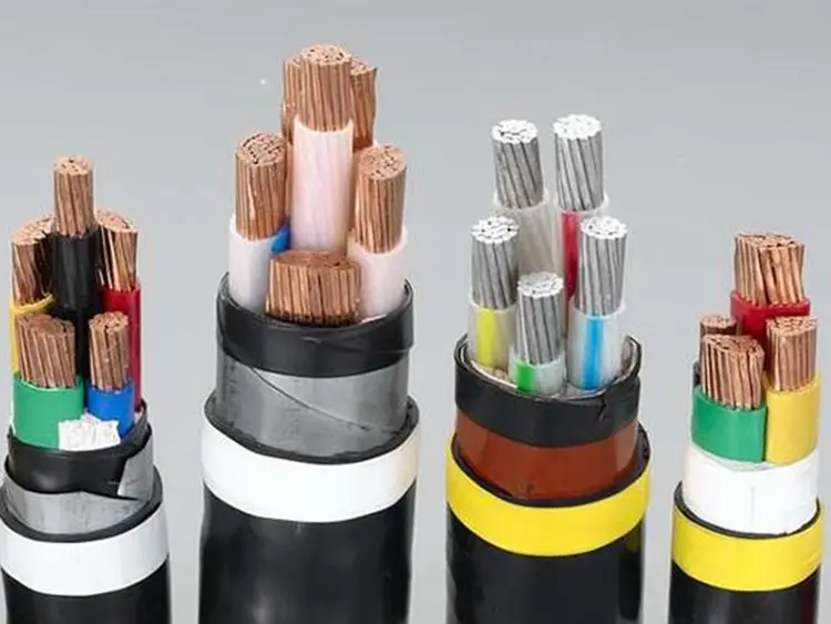
- During the signal transmission process, the wire pairs of the cable will interfere with each other and are also interfered by external signals. The twisted balance of the twisted pair and the shielding effect of the metal shielding layer can effectively prevent the intrusion of external electromagnetic interference signals and the leakage of electromagnetic radiation from inside the cable, and it has very good electromagnetic compatibility characteristics and confidentiality.
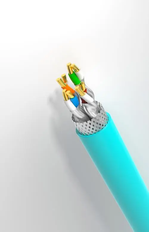
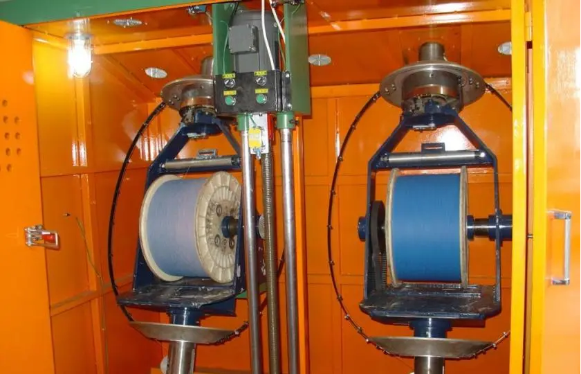
- Each pair of wires is shielded separately with aluminum foil longitudinally wrapped, and the thickness of the aluminum foil is appropriately increased. After the four pairs of wires are cabled, they are shielded longitudinally with aluminum foil, and the outermost layer is woven with metal wire for overall shielding. Due to the skin effect, reflection and absorption of the metal shielding layer, the surrounding electromagnetic field can be better separated and the crosstalk between the individually shielded pairs or between the four pairs of wires can be reduced. The metal wire can be tinned copper wire or tinned copper clad aluminum-magnesium alloy wire. Providing a separate aluminum foil shield for each pair of wires can eliminate the crosstalk between the pairs of wires and eliminate and reduce the electrical interference of the environment, improve electromagnetic compatibility, and avoid wrinkles in the longitudinal aluminum foil to ensure the shielding effect and transmission performance. The line pair shielding and the overall screen can be completed simultaneously in one step, which can not only improve production efficiency, but also reduce the damage to the line and pitch and the stretching of the conductor due to the multi-step process flow, which can greatly improve the product performance indicators.
- Under the condition of meeting the same production capacity, the one-step method has lower investment cost and higher production efficiency than the two-step method. Cabling can be equipped with a pay-off device with adjustable back-twist function and a cantilever single-twisting cabling machine with few turns to prevent the twisted pairs from changing the wire pair structure due to too many turns, and ensure that the twisted pair pitch and shielding of the four pairs will not change during cabling.
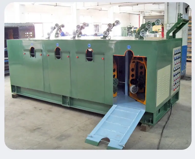
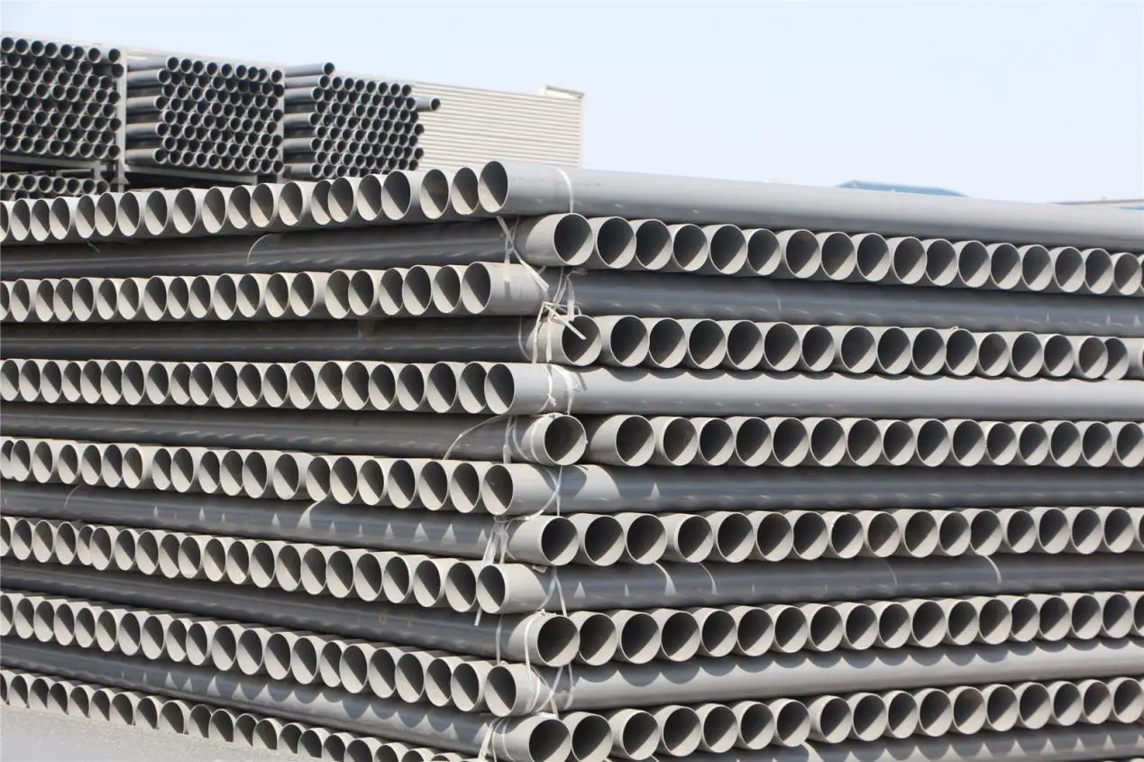
4. Finished product extrusion process control
Although finished product extrusion is the last step in production, the control elements are not as numerous and demanding as the previous steps. However, if the details such as extrusion die selection, wire laying, drawing, and coiling are not well controlled, the product transmission performance and bandwidth will also be affected. First of all, it is recommended to use an active wire laying device with active wire laying tension adjustment for the wire laying part; secondly, the extrusion inner and outer molds should be reasonably selected, the inner mold does not damage the woven mesh, and the outer mold should not be too large or too small. The traction adopts belt traction with few turns, and the coil is closed online to avoid secondary closing to stretch the product and other adverse damage. The wire reel meets the product bending radius requirements. During the production operation, personnel should pay attention to prevent adverse factors that affect the transmission performance, such as product twisting.
Conclusion
To produce qualified Category 7 and Category 8 digital communication cables, each link must be strictly controlled. Personnel in each process must fully understand the process requirements and equipment operation and receive qualified training before taking up their posts. At the same time, the stability and accuracy of the production equipment must be guaranteed to ensure that the finished product's characteristic impedance, attenuation, near-end crosstalk, far-end crosstalk, return loss, phase delay and other indicators have sufficient margins to meet the frequency and transmission rate requirements.